
Oregon Ions
Anja Bedrick and David Allcock

Transcript
Overview
A digitally drawn comic in the style of a complex infographic.
Cover
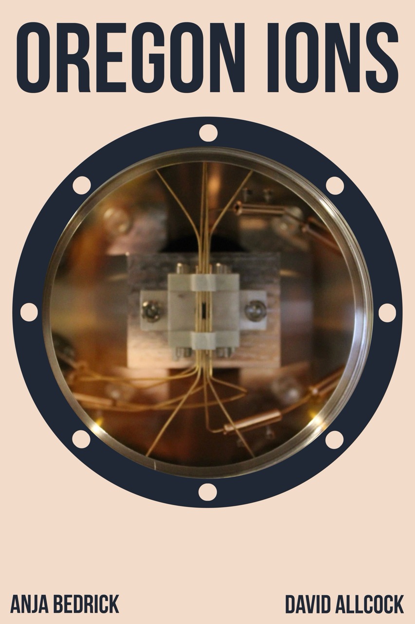
Oregon Ions
Anja Bedrick
David Allcock
Cover description: a circular window. Within the window is a photo of an ion trap.
Page 1
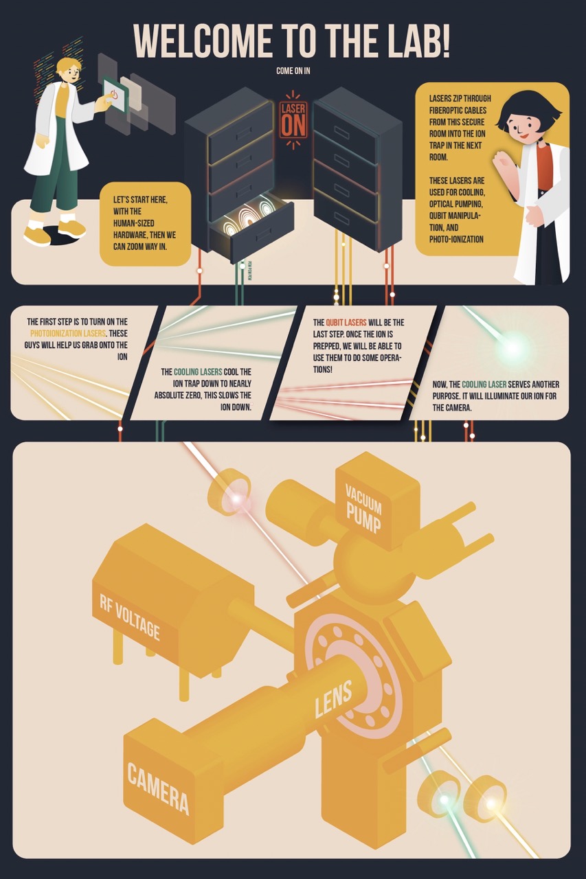
Panel 1: “Welcome to the lab! Come on in.” A woman with a pixie cut wearing a lab coat presses a power button panel. “Let’s start here, with the human sized hardware, then we can zoom way in.”
What look like two bulky grey sets of drawers take up the center of the panel. Above them is a sign that says “Laser ON.” Each drawer glows a different color: blue, red, yellow, or orange. The bottom drawer of one of the lasers is open. Inside the drawer are three spools of glowing cables: one is blue, one is red, one is yellow. Cables extend from the bottom of the drawers and leave the panel. They are thick stripes of red, green, and yellow with white dots periodically along the stripes. One line is labeled “pew pew pew”
A dark-haired woman in a lab coat stands near the lasers. “Lasers zip through fiberoptic cables from this secure room into the ion trap in the next room. These lasers are used for cooling, optical pumping, qubit manipulation, and photo-ionization.”
Panel 2: “The first step is to turn on the photoionization lasers. These guys will help us grab onto the ion.” Yellow lasers shoot through the panel.
Panel 3: “The cooling lasers cool the ion trap down to nearly absolute zero, this slows the ion down.” Green lasers shoot through the panel.
Panel 4: “The qubit lasers will be the last step. Once the ion is prepped, we will be able to use them to do some operations!” Red lasers shoot through the panel.
Panel 5: “Now, the cooling laser serves another purpose. It will illuminate our ion for the camera.” A single green laser shoots through the panel.
Panel 6: A diagram of the laser set up. The center of the diagram is a hexagon shape with a circle in the middle of it. A camera with a lens points into the center of a machine. On top of the hexagon is a vacuum pump. On the left side of the center hexagon a large hexagonal cylinder is attached labeled ‘RF voltage.’ On the lower right side of the hexagon a cooling laser and a photoionization laser shoot through lenses into the side of the hexagon. On the top left side of the hexagon a qubit laser shoots through a lens into the hexagon.
Page 2
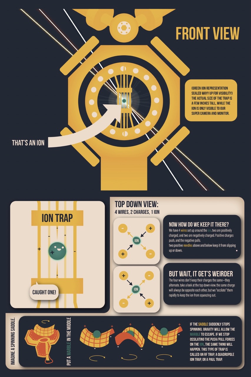
Panel 1: A front view diagram of the same machine, looking at the hexagon head on. Inside the hexagon is a circle, inside the circle are several wires connected to a rectangle forming a cage-like structure. In the center of the ‘cage’ is a small green dot with the label “that’s an ion.” Three laser beams enter on one side of the hexagon and intersect the ion, then exit the other side of the hexagon. “(Green ion representation scaled way up for visibility). The actual size of the trap is a few inches tall, while the ion is only visible to our super camera and monitor.”
Panel 2: “Ion Trap” A diagram of the ion trap. There are two thick horizontal, parallel rectangles at the top and bottom of the trap. Four wires run from the top of the panel to the bottom of the panel. A smiling ion is trapped within the wires, like it is in a cage. There are two negative wires and two positive wires that form a square around the ion. The wires alternate negative and positive. The ion is positive, and there are two small needles directly above and below the ion (within the wires) that further trap the ion. “Caught one!”
Panel 3: “Top Down View: 4 wires, 2 charges, 1 ion” A diagram of the ion trap from the top down, so the wires look like circles (as if you are viewing a cross-section). There are five circles arranged like the five pips on a die, with one circle in the center and four circles in a square around the center. The center circle is an ion. The top left and bottom right circles are ‘negative’ wires and arrows point out from the ion towards the negative circles. The top right and bottom left circles are positive wires, and arrows point from the positive circles towards the ion.
“Now how do we keep it there? We have 4 wires set up around the ion. Two are positively charged, and two are negatively charged. Positive charges push, and the negative pulls. Two positive needles above and below keep it from slipping up or down.”
The same diagram, but the polarity of each of the wires have inverted so the positive circles are in upper left and lower right-hand corners.
“But wait, it gets weirder. The four wires don’t keep their charges the same – they alternate. Take a look at the top down view The same charge will always be opposite each other, but we “oscillate” them rapidly to keep the ion from squeezing out.”
Panel 4: “Imagine a spinning saddle.” A saddle with stirrups, an arrow indicates it is spinning. On top of the seat portion of the saddle is an additional layer, that molds to the shape of the seat (i.e. a plane that curves up on either long side and curves down on the short sides – to fit the shape of a horse’s body). The plane has a grid superimposed on it to help show depth.
“Put a marble in the middle [of the saddle]”
Now we see just the saddle shaped-plane with a marble in the center, it does a full 360 degree rotation.
“If the saddle suddenly stops spinning, gravity will allow the marble to escape. If we stop oscillating the push/pull forces of the ion, the same thing will happen. This type of trap is called an RF trap, a Quadropole Ion Trap, or a Pual Trap.”
Page 3
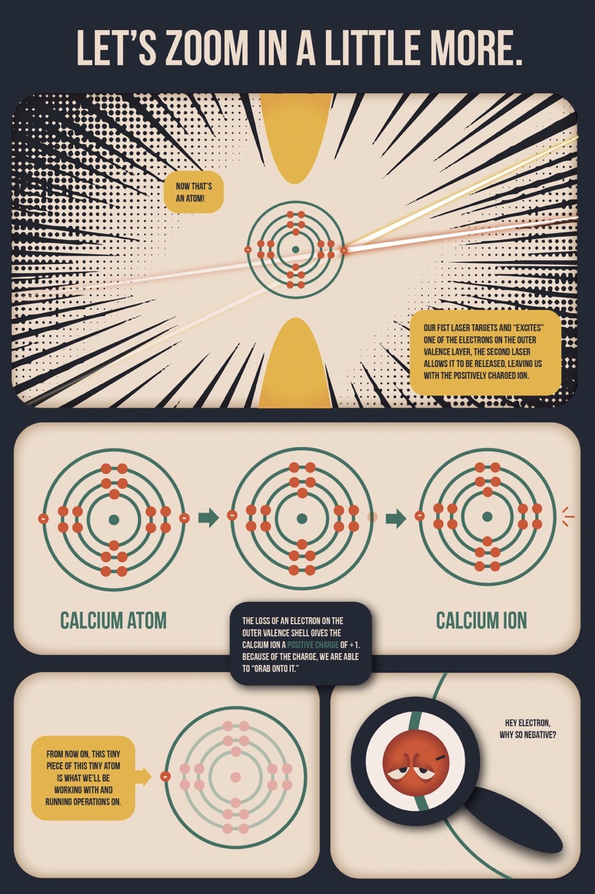
Panel 1: “Let’s zoom in a little more.”
“Now that’s an atom!”
“Our first laser targets and ‘excites’ one of the electrons on the outer valence layer, the second laser allows it to be released, leaving us with the positively charged ion.”
A zoomed in diagram of an atom between two needles. There is a nucleus in the center and 4 concentric circles around the nucleus (valence shells), there are two electrons on the inner most layer, 8 electrons on the next layer, 8 electrons on the third layer and two electrons on the outermost layer. The photoionization laser hits one of the electrons, and the qubit laser hits the same electron.
Panel 2: “Calcium Atom” A diagram shows a calcium atom losing one electron from its outer valence shell, becoming a “Calcium Ion”
“The loss of an electron on the outer valence shell gives the calcium ion a positive charge of +1. Because of the charge, we are able to ‘grab onto it.’”
Panel 3: “From now on, this tiny piece of this tiny atom is what we’ll be working with and running operations on.” This panel shows the same diagram of a calcium ion as panel 2, the solo electron in the outer valence shell is now highlighted.
Panel 4: “Hey electron why so negative?” A magnifying glass shows a frowning face on the electron.
Page 4
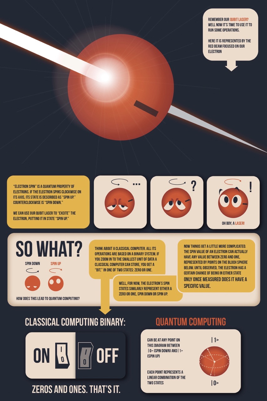
Panel 1: “Remember our Qubit laser? Well now it’s time to use it to run some operations. Here it is represented by the red beam focused on our electron.” An electron dominates the panel, a red laser (the qubit laser) bisects the electron.
Panel 2: “‘Electron spin’ is a quantum property of electrons. If the electron spins clockwise on its axis, its state is described as ‘spin up.’ Counterclockwise is ‘spin down.’ We can use our qubit laser to ‘excite’ the electron, putting it in state ‘spin up.’”
Panel 3: The electron looks sad and tired, an arrow indicates it is spinning counterclockwise “…”
Panel 4: The electron continues to spin counterclockwise; it looks confused.
Panel 5: The electron starts to spin clockwise and gets excited. “Oh boy, a laser!”
Panel 6: “So what? How does this lead to quantum computing?” In a simplified, symbolic style, side-by-side, the tired counterclockwise electron labeled “spin down” and the big-eyed clockwise electron labeled “spin up.”
“Think about a classical computer. All its operations are based on a binary system. If you zoom in to the smallest unit of data a classical computer can store, you get a ‘bit,’ in one of two states: zero or one.”
“Well, for now, the electron’s spin states similarly represent either a zero or one, spin down or spin up.”
“Now things get a little more complicated. The spin value of an electron can actually have any value between zero and one, represented by points on the Bloch sphere below. Until observed, the electron has a certain chance of being in either state. Only once measured does it have a specific value.”
Panel 7: “Classical computing binary:” A panel that shows a switch in two positions: “on” and “off” “Zeros and ones. That’s it.”
Panel 8: “Quantum Computing:” “Can be at any point on this diagram between | 0> (spin down) and | 1> (spin up). Each point represents a linear combination of the two states.” A Bloch sphere diagram with a horizontal dotted line around the circumference. At the center of the sphere is a dot with axis arrows pointing out from the dot to the edge of the sphere. Several lines are drawn in, but only two are highlighted (one pointing diagonally up and one pointing diagonally down). Outside of the sphere are two labels, at the top of the sphere is “| 1>” at the bottom of the sphere is “| 0>”
Page 5
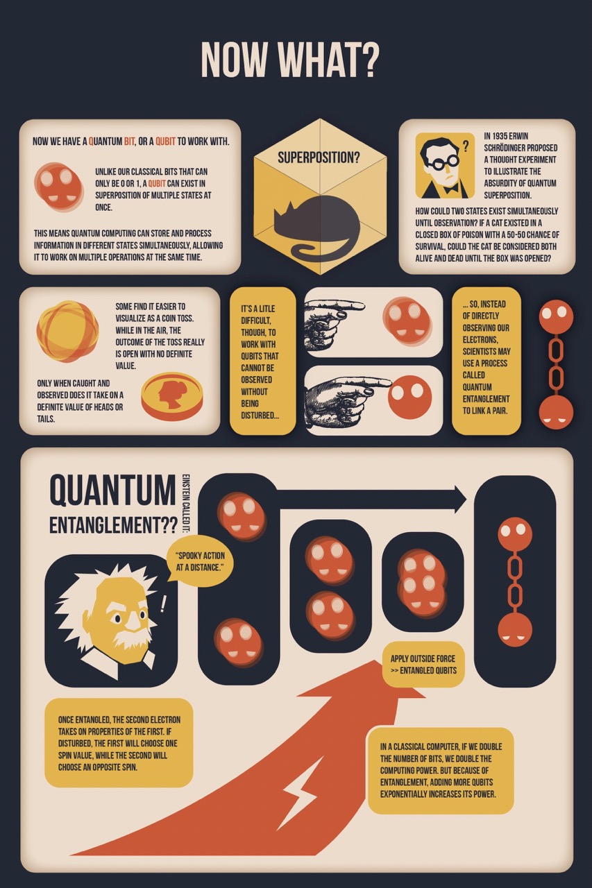
Page Title: “Now What?”
Panel 1: “Now we have a quantum bit [highlight Q…BIT], or a qubit to work with. Unlike our classical bits that can only be 0 or 1, a qubit can exist in superposition of multiple states at once. This means quantum computing can store and process information in different states simultaneously, allowing it to work on multiple operations at the same time.” An atom, blurred to show that it’s in two positions at once. In one of the positions the atom is in the ‘spin down’ state. In the other it is in the ‘spin up’ state (excited).
Panel 2: A translucent box, inside of which is the silhouette of a sleeping cat. “Superposition?”
Panel 3: “In 1935 Erwin Schrödinger proposed a thought experiment to illustrate the absurdity of quantum superposition. How could two states exist simultaneously until observation? If a cat existed in a closed box of poison with a 50-50 chance of survival, could the cat be considered both alive and dead until the box was opened?” A small drawing of Schrödinger, a middle-aged man with dark hair, round glasses, and a bowtie.
Panel 4: “Some find it easier to visualize as a coin toss. While in the air, the outcome of the toss really is open with no definite value. Only when caught and observed does it take on a definite value of heads or tails.” A coin spins through the air, landing on heads.
Panel 5: “It’s a little difficult, though, to work with qubits that cannot be observed without being disturbed…”
Panel 6: A retro style drawing of a finger pointing at the blurry superposition of the spin up and spin down atoms.
Panel 7: A retro style drawing of a finger pointing. This time the finger is touching the atom and the atom isn’t blurry (i.e. it’s in a single position).
Panel 8: “…So, instead of directly observing our electrons, scientists may use a process called quantum entanglement to link a pair.” Two electrons are linked by a chain, one is in ‘spin up’ state and one is ‘spin down’ state.
Panel 9: “Quantum Entanglement?? Einstein called it: ‘Spooky action at a distance.’” Portrait of an excited Einstein with stylized spiky white hair.
Sub-panels 1-4: in the first panel two electrons in superposition are about an inch apart. An arrow of electricity forces the electrons together. In consecutive panels the electrons move closer until they overlap. “Apply outside force >> entangled qubits”. In the final panel the electrons are connected with a chain and no longer in superposition, instead one is ‘spin up’ and one is ‘spin down.’
“One entangled, the second electron takes on properties of the first. If disturbed, the first will choose one spin value, while the second will choose an opposite spin.”
“In a classical computer, if we double the number of bits, we double the computing power. But because of entanglement, adding more qubits exponentially increases its power.”
Page 6
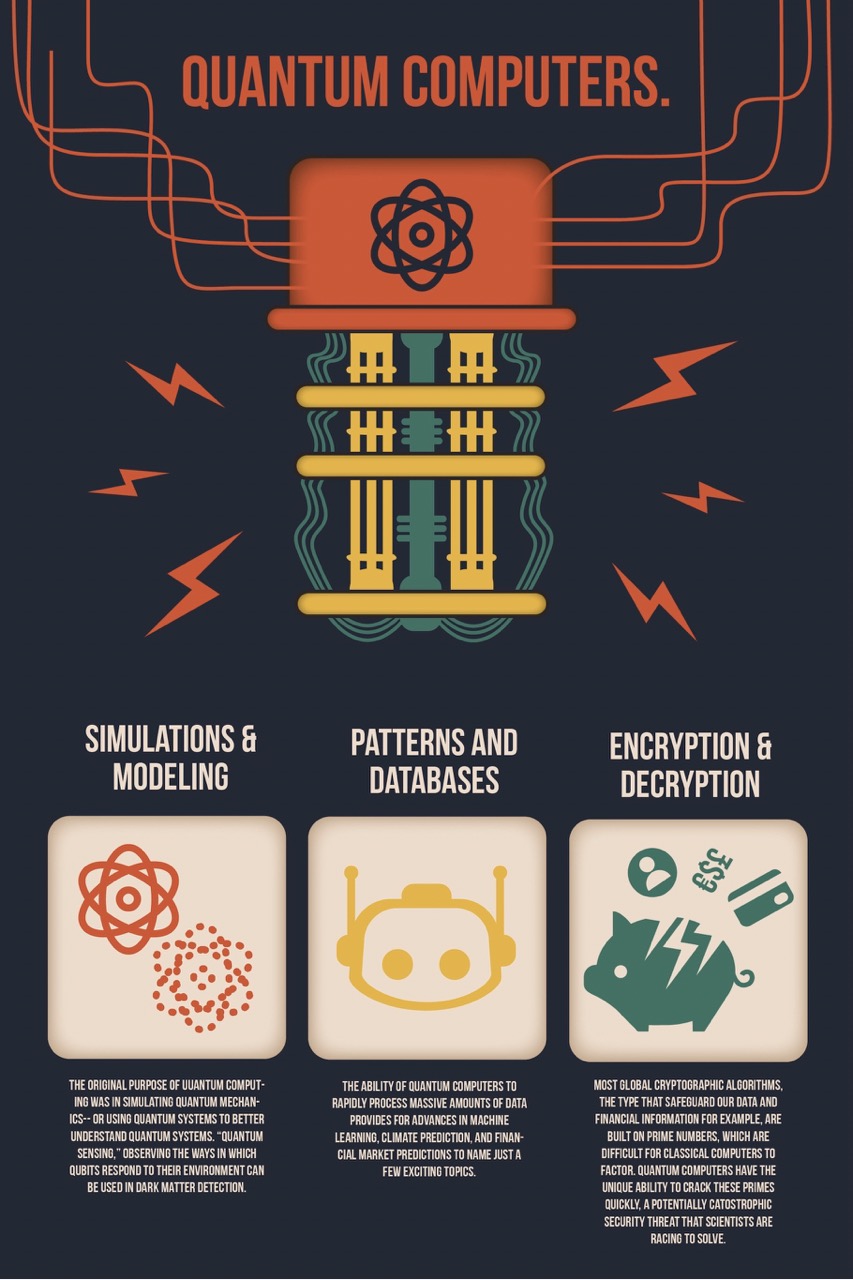
Panel 1: “Quantum Computers.”
A simplified diagram of a quantum computer shows a large rectangle with a cartoon of an atom on it and lots of snaking wires connect to it. More wires and tubes come out of the bottom of the device. Bolts of electricity surround the computer.
Panel 2: “Simulations & Modeling” Two cartoon drawings of atoms, one with solid lines, the other with dotted lines. “The original purpose of Quantum computing was in simulating quantum mechanics— or using quantum systems to better understand quantum systems. “Quantum sensing,” observing the ways in which qubits respond to their environment can be used in dark matter detection.
Panel 3: “Patterns and Databases.” A cartoon symbol of a robot’s head. “The ability of quantum computers to rapidly process massive amounts of data provides for advances in machine learning, climate prediction, and financial market predictions to name just a few exciting topics.”
Panel 4: “Encryption & Decryption” a broken piggy bank with symbols for: a person, British pounds, US dollars, the euro, and a credit card falling out of it. “Most global cryptographic algorithms, the type that safeguard our data and financial information for example, are built on prime numbers, which are difficult for classical computers to factor. Quantum computers have the unique ability to crack these primes quickly, a potentially catastrophic security threat that scientists are racing to solve.”
Back Cover
Page Title: “Meet the Oregon Ions:”
This page shows 11 photos of Oregon Ion lab members, their names, and titles.
David Wineland, Research Professor.
David Allcock, Assistant Professor & Laboratory Principal Investigator.
Alex Quinn, Graduate Student.
Daniel Moore, Graduate Student.
Jeremy Metzner, Graduate Student.
Sean Brudney, Graduate Student.
Gabe Gregory, Graduate Student.
Genevieve Wages, Undergraduate Student.
Aaron Casserly, Undergraduate Student.
Marcus Polk, Undergraduate Student.
Anja Bedrick, Illustrator.
About the authors

name: Anja Bedrick
website: https://www.anjabedrick.com/
Anja Bedrick is a designer with a background in Art&Technology and Political Science currently pursuing a masters in interaction design.